Power Supplies

A range of box sizes are available for Elmdene power supplies. Use the table below to identify the box size for your application.

Box
Reference
Dimensions (mm) PSU Range and Maximum Battery Capacity
H W D Lid Type 12V Max Battery Size 24V Max Battery Size
A 200 230 80 Hinge N-Range: 1A-3A
BM-Range: 1A-2A
GEN2/GEN3-08
1 x 7Ah TR-Range
(no Battery)
N/A
B 330 355 80 Clam N-Range: 4A-5A
BM-Range: 3A-5A
GEN2/GEN3-08
GEN2/GEN3-18
1 x 17Ah N/A N/A
B2 380 334 85 Hinge ACCESS-PSU1
POE-ULTRAPOD-B
1 x 17Ah N/A N/A
C 275 330 80 Hinge N-Range: 1A-5A
BM-Range: 1A-10A
GEN2/GEN3-08
GEN2/GEN3-18
G12-24 Range
1 x 17Ah N-Range: 1A-5A
BM-Range: 1A-10A
STX-Range: 1A-5A
ST/ STV Range: 1A-5A
G12-24 Range
2 x 7Ah
D 500 400 80 Hinge ACCESS-PSU2
ACCESS-PSU2-8A
ACCESS-UL-PSU2
1 x 17Ah N/A N/A
E 420 400 80 Hinge N/A N/A STX-Range: 2A-10A
ST/ STV Range:1A-5A
2 x 17Ah
F 380 230 75 Hinge GEN3-08-F 1 x 7Ah N/A N/A
G 440 250 115 Hinge ACCESS-UL-PSU1 1 x 7Ah N/A N/A
H 420 420 180 Hinge G12-24 Range: 63/84  1 x 38Ah BM-Range: 5A
STX-Range: 10A
ST/ STV Range: 2A-5A
G12-24 Range: 63/84 
2 x 38Ah
J 185 200 53 Hinge VRS124000 Range: 4A
(no Battery)
N/A TRS1 Range: 1A
(no Battery)
N/A
K 325 350 105 Hinge N/A N/A ST/ STV Range: 2A-5A 2 x 17Ah
(inc. 2 x 12Ah)
M 182 182 90 IP66 N/A N/A VR24x0-P Range: 4A-6A N/A
P 250 150 100 IP68

 VRS124000-xP Range    VRS122000-PTC-P

N/A N/A N/A
Q 200 200 100 IP66 N/A N/A VR2480-xP Range: 8A N/A
R 410 390 86 Clam GEN3-34-R 2 x 17Ah N-Range: 1A-5A
BM-Range: 1A-5A
G12-24 Range: 63/84
2 x 17Ah
S 345 288 90 Clam VRS1216000-16-S (16A)
VRS1220000-24-S (20A)
N/A VR24160-8-S (16A)
VR24160-16-S  (16A)
N/A
T 300 240 60 Hinge

VRS12x000 Range:    4-8A

N/A STX/ST/STV Range: 1A
VR2480-xT Range: 8A
2 x 1.2Ah
N/A
V 515 478 146 Hinge MULTI-ACCESS-PSUx
MULTI-ACCESS-UL-PSU6
1 x 17Ah MULTI-ACCESS-PSUx 2 x 7Ah

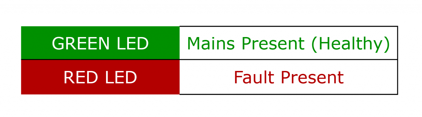
Depending on the PSU range, the PSU will detect and provide visual status that a fault is present, this can include any of the following:

  • Loss of mains
  • Output fuse fail
  • Battery fuse fail
  • Output short circuit
  • Low output voltage
  • Battery disconnected


​​​​​​​The BM, GEN and EN54-4 ranges provide additional Fault diagnostic LED indications, providing the installer with more detailed information.

See specific range manuals for details.


The most common causes of battery fault condition are:

  • Battery fuse has failed – confirm with multi-meter, replace with correct size & type
  • Poor connection – Check all crimp connections, ensure good contact and no corrosion is present
  • The battery is badly aged or damaged (note: battery life can be shortened by very high ambient temperature), check condition with meter / battery tester and replace with new version as required (observe polarity)
  • For EN54-4 Fire power supplies, ensure temperature sensor is fitted – if not connected or bad connection is present a battery fault will be present
  • Is the correct battery fitted? 12V PSUs don’t like 24V batteries, and 24V PSUs may not recognise a 12V battery, or try to overcharge it!
  1. Disconnect the battery and measure its potential to see if it falls within the expected range
  2. Reconnect the battery to the PSU, ensure the PSU is running, and measure the potential of the battery and charge current. If the battery potential does not rise even slightly, after a few minutes, or no charging current can be seen, the charger is likely to be faulty, or the battery is heavily damaged
  • Most of our power supplies utilise 20mm glass fuses for PSU, battery & load protection. Before replacing any fuse, it is good practice to check for any obvious causes of the fuse failure (i.e. short circuits)
  • When replacing any fuse, for your safety, ensure the mains supply (and battery connection) are disconnected, remove the suspect fuse and check with a multi-meter, if confirmed blown replace with the correct type and size
  • Replacement 20mm glass fuses can be found at all main electronic distributors. For the mains fuse, do not be tempted to insert the fuse without its holder / carrier (cover), and only use HRC rated fuses for the mains connection
  • For the low voltage output and battery fuses, use only F (Fast blow) fuses

If in doubt of fuse selection – please contact Elmdene Technical Support

  • Failure of output fuse due to overload
  • PSU has shut down due to overload
  • Action Disconnect load, replace fuse if required, check output & load before reconnecting. If failure occurs again, check load for faults

Overload condition: Check current being drawn by load with ammeter / disconnect load and check output voltage is correct for power supply.

  • This is not usually a fault; where a power supply has Battery Deep Discharge Protection, a charge voltage will not be present until a ‘healthy’ battery is connected.
  • This would be a battery or batteries with a terminal voltage of approximately 11V for a 12V PSU, and 23V for a 24V PSU.

Note: True battery charge voltage can only be measured with the battery(ies) connected to the power supply.

Magnetic Contacts

  • The colour coding is referring to what the magnetic contact is pre-resistored to.
  • A typical part code for an Elmdene contact reads as LST-GN, where GN = Green, referring to the value of the shunt and end-of-line resistors integral with the contact. See table below of other colour references.
  • The resistor pair colour references should not be confused with short coloured sleeves, slipped over the contact wire-ends, to aid with installation.


Elmdene Magnetic Contacts
Resistors Colour Code Control Panels
4k7/2k2 Red RD ADE, Bosch, Castle, Dycon, Menvier, Pyronix, Scantronic, Texecom
1k/1k Green GN Honeywell, Galaxy
8k2/8k2 Blue BL Guardall
4k7/4k7 Grey GY Aritech, HKC, Siemens
6k8/4k7 Purple PU GardTec
2k2/2k2 Yellow YL Europlex
5k6/5k6 Orange OR DSC
22k/10k Brown BRN Texecom Veritas


Please get in touch with us if you need assistance with this matter. High Security Contact internal technical details are not published.

  • Fully Supervised Loop (FSL) is a connection arrangement designed to economise on wiring to a control panel by combining the alarm and tamper detection functions in one circuit (a single pair of wires connects to the control panel).
  • Double Pole is a connection arrangement which takes advantage of control panels which provide an input connection pair for Alarm sensing and another separate input connection pair for Tamper detection.
  • A SHUNT resistor is the resistor (or multiple resistors) ‘shunted’ (bypassed) by the magnetically operated reed switch, within the contact assembly, when in non-alarm condition and so this resistor appears as a short circuit. When the reed switch opens (alarm condition) the shunt resistor(s) appear in the circuit again.
  • An EOL (End of Line) resistor is the resistor which is placed ‘at the end of the line’ (far end of the circuit), within the contact assembly, and will be the value of resistance seen by the control panel, in non-alarm condition.
  • A Series contact is wired or optimised for shunting out, only the shunt (series) resistor in non-alarm condition and re-instating the shunt resistor (series additive) in alarm condition.
  • A Parallel contact is wired or optimised for placing the EOL and Shunt resistors in parallel, in non-alarm condition, and disconnecting the shunt resistor (leaving only EOL resistor) in alarm condition.

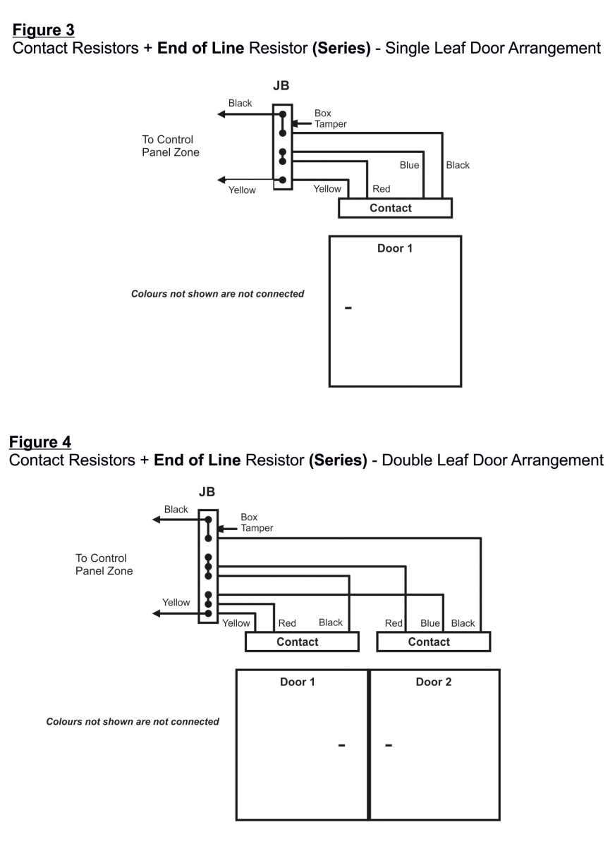
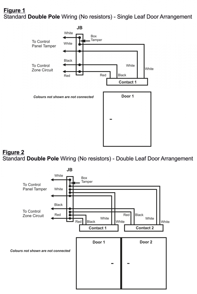
Please refer to diagrams

For all Panels except Guardall:


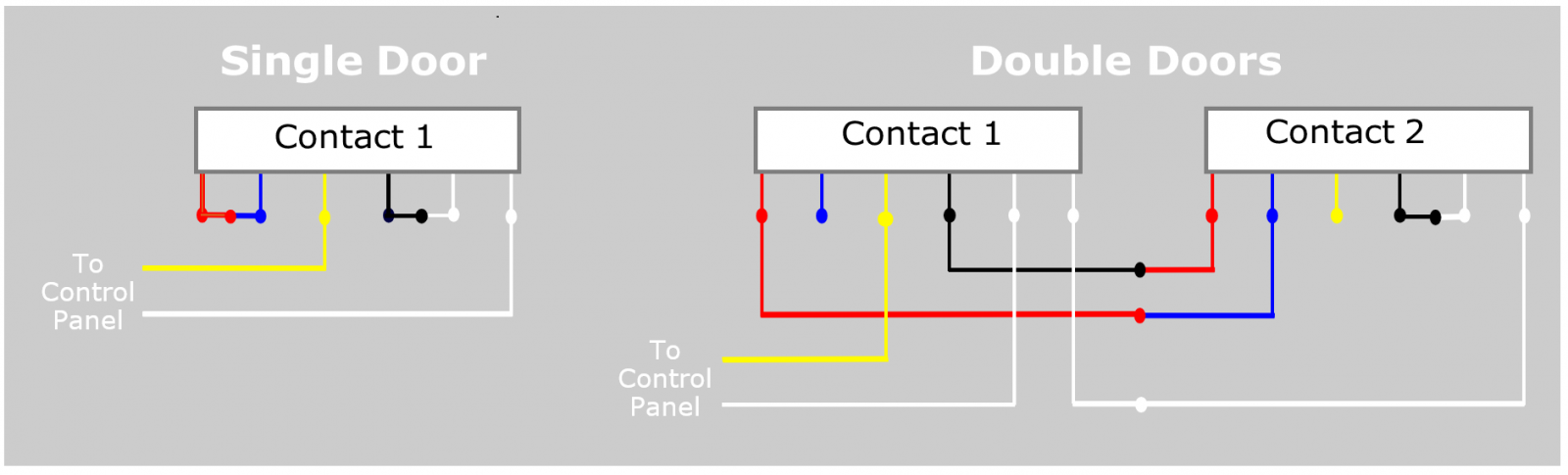
For 6-wire contacts, No resistors:


6 Wires contacts, with Resistors: